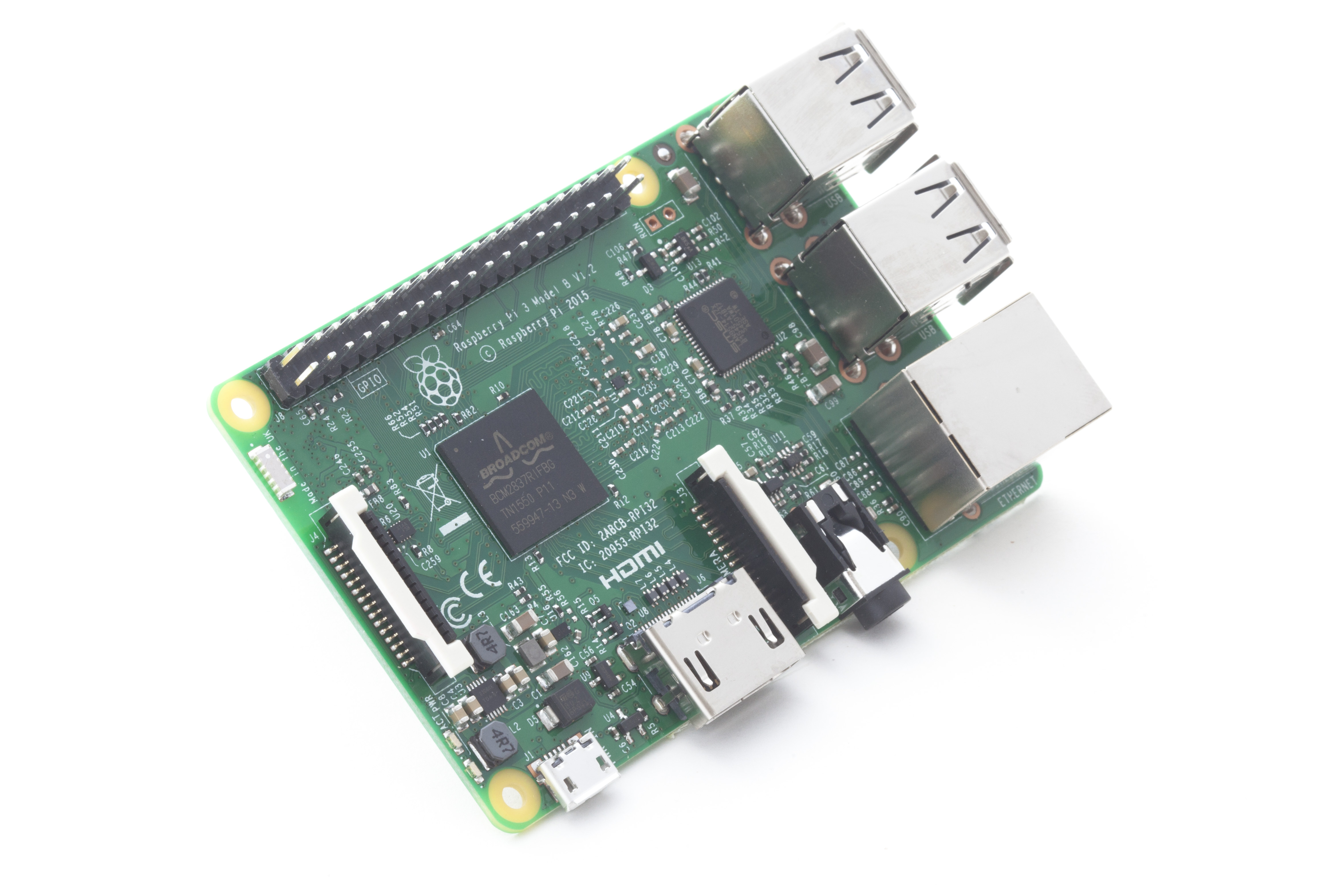
The [Raspberry PI 3] is now on sale for $35. This increases the RAM to 1GB. The 64-bit quad processor is 10 times faster than the original Raspberry PI. And now RPI3 comes with built-in wifi.
The Development Blog of Tim Graupmann
The [Raspberry PI 3] is now on sale for $35. This increases the RAM to 1GB. The 64-bit quad processor is 10 times faster than the original Raspberry PI. And now RPI3 comes with built-in wifi.
Adafruit has a [post] on how to turn your Raspberry PI into a USB device that can connect to your computer like a peripheral. This could be useful for a ton of projects.
Idea wall:
1) A custom audio device that can change the pitch using the input from a guitar pickup.
2) A multiple camera device to auto switch to the camera being looked at.
To use a camera with the Raspberry PI, first [configure the Raspberry PI] to enable the camera.
In order to send large images from the Raspberry PI camera to a web server, the image has to be sent in parts. This requires the Python `poster` module. https://pypi.python.org/pypi/poster/
To be able to install a python module, `pip` has to be installed.
sudo pip install poster
This is the server PHP page that saves the image.
<?php

$image = $_FILES["image"];

if ($image == null) {
   echo "Missing image to save!";
} else {
   echo "Saved image!";
   $tmp_name = $_FILES["image"]["tmp_name"];
   move_uploaded_file($tmp_name, "image.jpg");
}

?>
This Python script sends the image to the server.
#!/usr/bin/env python

import urllib, urllib2
from poster.encode import multipart_encode
from poster.streaminghttp import register_openers

register_openers()

url = "http://domain.com/path/save_image.php"
print "url="+url

filename = 'image.jpg';
if (os.path.isfile(filename)) :
  values = {'image':open(filename)}
  data, headers = multipart_encode(values)
  headers['User-Agent'] = 'Mozilla/4.0 (compatible; MSIE 5.5; Windows NT)'
  req = urllib2.Request(url, data, headers)
  req.unverifiable = True
  content = urllib2.urlopen(req).read()
  print (content)
else:
  print 'No image file found to upload';

print '\r\nProgam complete.'
This script will capture from the camera and then call the above script to upload the image.
#get access to the camera
from picamera import PiCamera

#import so we can invoke another script
import subprocess

#sleep so we can wait on the camera
from time import sleep

# create a camera object
camera = PiCamera()

#set the image resolution
camera.resolution = (320, 240)

#rotate the camera if upside-down
camera.rotation = 180

#show preview with some transparency
camera.start_preview(alpha=225)

#wait two seconds for camera lighting
sleep(2)

#save image locally
camera.capture('image.jpg')

#stop the preview
camera.stop_preview()

#invoke the script to upload the image
subprocess.call('python save_image.py', shell=True)
Windows 10 can be installed on the Raspberry PI 2 from a free download.
http://ms-iot.github.io/content/Downloads.htm
The servo can be turned clockwise, counter clockwise, and to the 90 degree position, but it lacks a way to query the current rotation. The rotation needs to be calculated manually and this script is a first attempt.
#!/usr/bin/env python

import RPi.GPIO as GPIO
import datetime
import time

servo_pin = 22
servo_pin2 = 18

# 60 degrees / 0.1seconds
servo_speed = 0.1

GPIO.setwarnings(False)
GPIO.setmode(GPIO.BOARD)

GPIO.setup(servo_pin, GPIO.OUT)
GPIO.setup(servo_pin2, GPIO.OUT)

last_time = datetime.datetime.now()
current_time = datetime.datetime.now()
sumTime = datetime.timedelta(0, 0)

accuracy = 0.01
targetRotation = 0
currentRotation = 90

pulse1 = GPIO.PWM(servo_pin, 50)
pulse2 = GPIO.PWM(servo_pin2, 50)

logTime = datetime.datetime.now()

def log(msg):
 global deltaTime
 global logTime
 if (logTime < datetime.datetime.now()):
  logTime = datetime.datetime.now() + datetime.timedelta(0, 0.5)
  print msg
 return

def reset(pulse):
 pulse.start(7.5);
 pulse.ChangeDutyCycle(7.5)
 return

def update(pulse, targetRotation):
 global deltaTime
 global sumTime
 global servo_speed
 global accuracy
 global currentRotation
 log ("TargetRotation: " + str(targetRotation) + " CurrentRotation: "+str(currentRotation))
 if (targetRotation == 90):
  pulse.ChangeDutyCycle(7.5)
  if ((currentRotation - targetRotation) < -accuracy):
   currentRotation += servo_speed
  elif ((currentRotation - targetRotation) > accuracy):
   currentRotation -= servo_speed
  else:
   pulse.ChangeDutyCycle(0)
 elif ((currentRotation - targetRotation) < -accuracy):
  pulse.ChangeDutyCycle(12.5)
  currentRotation += servo_speed
 elif ((currentRotation - targetRotation) > accuracy):
  pulse.ChangeDutyCycle(2.5)
  currentRotation -= servo_speed
 else:
  pulse.ChangeDutyCycle(0)
 return

try:
 reset(pulse1)
 reset(pulse2)
 time.sleep(1)
 print "setup complete"

 while True:

  last_time = current_time
  current_time = datetime.datetime.now()
  deltaTime = current_time - last_time;
  sumTime += deltaTime;

  if (sumTime.total_seconds() > 3.0):
   #print (sumTime)
   sumTime -= datetime.timedelta(0, 3)
   targetRotation = (targetRotation + 45) % 180

  update(pulse1, targetRotation);
  update(pulse2, targetRotation);

  time.sleep(0);

except KeyboardInterrupt:

 print '\r\nProgam complete.'
 GPIO.cleanup();
Using pulse modulation, the Raspberry PI can adjust a servo.
https://www.youtube.com/watch?v=ddlDgUymbxc
![2015-04-22+12.06.15[1]](https://tagenigma.com/blog/wp-content/uploads/2015/04/2015-04-22-12.06.151.jpg)
Here I combined the LED blinking example with the servo example.
#!/usr/bin/env python

import RPi.GPIO as GPIO
import time
led_pin = 15
led_pin2 = 16
led_pin3 = 36
led_pin4 = 37

GPIO.setwarnings(False)
GPIO.setmode(GPIO.BOARD)

GPIO.setup(led_pin, GPIO.OUT)
GPIO.setup(led_pin2, GPIO.OUT)
GPIO.setup(led_pin3, GPIO.OUT)
GPIO.setup(led_pin4, GPIO.OUT)

GPIO.setup(22, GPIO.OUT)

p = GPIO.PWM(22, 50)
p.start(7.5);

try:
 while True:

  GPIO.output(led_pin, GPIO.HIGH)
  GPIO.output(led_pin2, GPIO.HIGH)
  GPIO.output(led_pin3, GPIO.HIGH)
  GPIO.output(led_pin4, GPIO.HIGH)
  p.ChangeDutyCycle(7.5)
  time.sleep(1)

  GPIO.output(led_pin, GPIO.LOW)
  GPIO.output(led_pin2, GPIO.LOW)
  GPIO.output(led_pin3, GPIO.HIGH)
  GPIO.output(led_pin4, GPIO.HIGH)
  p.ChangeDutyCycle(12.5)
  time.sleep(1)

  GPIO.output(led_pin, GPIO.HIGH)
  GPIO.output(led_pin2, GPIO.HIGH)
  GPIO.output(led_pin3, GPIO.HIGH)
  GPIO.output(led_pin4, GPIO.HIGH)
  p.ChangeDutyCycle(7.5)
  time.sleep(1)

  GPIO.output(led_pin, GPIO.HIGH)
  GPIO.output(led_pin2, GPIO.HIGH)
  GPIO.output(led_pin3, GPIO.LOW)
  GPIO.output(led_pin4, GPIO.LOW)
  p.ChangeDutyCycle(2.5)
  time.sleep(1)

except KeyboardInterrupt:

 print '\r\nBack to neutral...'
 p.ChangeDutyCycle(7.5)
 time.sleep(1)

 print '\r\nProgam complete.'
 GPIO.cleanup();
The following Python alternates between two LEDs and then goes dark before repeating.
![20150418_211943[1]](https://tagenigma.com/blog/wp-content/uploads/2015/04/20150418_2119431.jpg)
#!/usr/bin/env python

import RPi.GPIO as GPIO
import time
led_pin = 15
led_pin2 = 37
blinkSpeed = 5/2.0 #blink x times per second

GPIO.setwarnings(False)
GPIO.setmode(GPIO.BOARD)

GPIO.setup(led_pin, GPIO.OUT)
GPIO.setup(led_pin2, GPIO.OUT)

try:
 while True:

  GPIO.output(led_pin, GPIO.HIGH)
  GPIO.output(led_pin2, GPIO.LOW)
  time.sleep(blinkSpeed / 3.0)

  GPIO.output(led_pin, GPIO.LOW)
  GPIO.output(led_pin2, GPIO.HIGH)
  time.sleep(blinkSpeed / 3.0)

  GPIO.output(led_pin, GPIO.LOW)
  GPIO.output(led_pin2, GPIO.LOW)
  time.sleep(blinkSpeed / 3.0)

finally:
 print 'finally'
Here’s a short Python script to toggle an LED using GPIO.
![20150418_173116[1]](https://tagenigma.com/blog/wp-content/uploads/2015/04/20150418_1731161.jpg)
#!/usr/bin/env python

import RPi.GPIO as GPIO
import time
pin = 15
blinkSpeed = 1/5.0 #blink x times per second
GPIO.setmode(GPIO.BOARD)
GPIO.setup(pin, GPIO.OUT)
try:
 while True:
  print('PIN {} is going HIGH'.format(pin))
  GPIO.output(pin, GPIO.HIGH)
  time.sleep(blinkSpeed / 2.0)
  print('PIN {} is going LOW'.format(pin))
  GPIO.output(pin, GPIO.LOW)
  time.sleep(blinkSpeed / 2.0)
finally:
 print 'finally'
To make a Raspberry PI 2 Laptop, all you need is a mouse, keyboard, and TFT display. The battery is optional.
http://techcrunch.com/2015/04/17/this-diy-raspberry-pi-laptop-is-perfect-for-your-weekend-machinations/?ncid=rss
I’ve wanted to play my Cello with RockSmith but the octave needs to be adjusted. This DIY project shows how to make your own tone cable and I could use the Raspberry PI to adjust the pitch.
http://makezine.com/2015/01/30/for-those-about-to-rocksmith-hack-a-custom-cable/
Maybe I can sacrifice one of my old scales to repeat this detailed project and connect to the Raspberry PI 2.
https://www.youtube.com/watch?v=fPzUtzFJFus
I’ll graph the results using ChartsJS.
http://www.chartjs.org/
Installing Sails.js required building and installing Node.js from source.
I let the source build overnight and then moments later ‘sails lift’ was functional.
https://github.com/tgraupmann/TAGENIGMA-Docs/blob/master/Sails.md
Also the reference guide is super helpful.
http://sailsjs.org/#!/documentation/reference/
Here is also a useful C# client:
https://github.com/Quobject/SocketIoClientDotNet
I picked up a Raspberry PI 2 and it’s working super speedy. Quad-core 900 MHz, ARM, 4-usb, HDMI/audio out.
http://www.amazon.com/CanaKit-Raspberry-Ultimate-Starter-Components/dp/B00G1PNG54/
After settting up WIFI, installing VNC made connecting the display, mouse, and keyboard no longer necessary. The boot process can be altered to start VNC server automatically.
https://www.raspberrypi.org/documentation/remote-access/vnc/